1, Multiplier Circuit, design a 4 x 4 binary multiplier circuit.

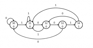
2, Write VHDL code to implement the FSM described in the state graph below.
Library ieee;
Use ieee,std_logic_1164.all;
Entity M1 is
Prot (clk,Resetn: in std_logci;
X: in std_logic;
Y : out std_logci);
End M1;
Architecture behavioral of M1 is
Type state_type is (s0, s1, s2, s3, s4);
Signal Qpresent, Qnext: state_type;
Begin
Next_state: process(x, Qpresent)
Begin
Case Qpresent is
When s0=>
If (x=’0’) then Qnext <= s0;
Else Qnext <= s1;
End if;
When s1=>
If (x=’0’) then Qnext <= s2;
Else Qnext<=s1;
End if;
When s2=>
If (x=’0’) then Qnext <= s3;
Else Qnext<=s1;
End if;
When s3=>
If (x=’0’) then Qnext <= s0;
Else Qnext<=s4;
End if;
When s4=>
If (x=’0’) then Qnext <= s2;
Else Qnext<=s1;
End if;
End process;
State_reg: process(clk, Resetn)
Begin
If (Resetn=’0’) then
Qpresent <= s0;
Elsif (clk’ event and clk=’1’) then Qpresent<=Qnext;
End if;
End process;
Y<=’1’ when (Qpresent = s4) else ‘0’;
End behavioral;